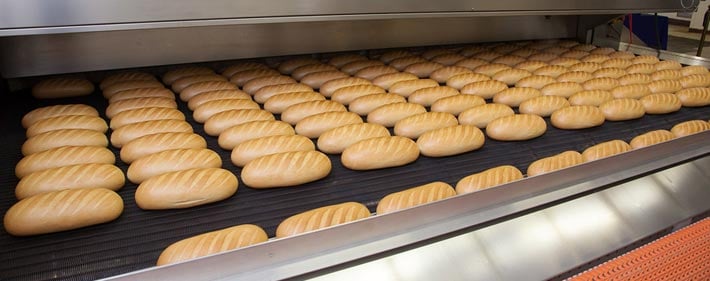
The view of parallel rolls is a beautiful thing - and not just the rolls that often accompany your favorite pasta dish! We're talking about industrial rolls. When they're precisely parallel, they produce faster throughput, higher quality, and more uptime.

Rolls that are not precisely parallel might result in problems like:
- Vibration
- Premature roll and bearing wear
- Improper web tracking, wrinkling and tearing
- Uneven coatings
- Substandard registration
We're often asked how to make rolls (or other components) parallel. One way to approach the job would be like this:
- Establish a reference line running parallel to the entire machine (so that ideally, all rolls would be perpendicular to this line).
- Set up an instrument to turn a precise right angle from this reference line.
- Measure the orientation of each roll, using the instrument at right angles to the reference line.
Let's take a closer look at each of these steps.
Step 1
There are several ways to establish the reference line which runs parallel to the entire machine, but let's use a somewhat typical situation. Suppose that an "offset centerline" is marked by floor monuments near the machine. This is a line which is parallel to the machine centerline, which was established by floor markers at some time in the past. Picture a vertical plane rising up through these floor markers. We can set up a model 76-RH transit so that it is directly in line with this vertical plane, and pointing in the direction established by the floor markers. We'll call this instrument "A". When this is done, instrument "A" can be used as the reference because it has been set exactly parallel to the machine centerline. We set the focus of this instrument at infinity and turn on the reticle illumination light.
Step 2
Next, we set up another model 76-RH transit somewhere near one of the rolls that we want to measure. We'll call this instrument "B". Remember that the 76-RH has a horizontal cross-axis telescope permanently focused at infinity, which is mounted exactly perpendicular to the main telescope. When we point the main telescope of instrument B toward the rolls, its cross telescope will be pointing back at transit A. Since we focused A's telescope at infinity and illuminated its reticle, we can collimate B's cross-telescope on the reticle in A's main telescope. This alignment process causes the main telescope of B to become exactly perpendicular to the main telescope of A. Accordingly, the main telescope of instrument B can now sweep a plane which is perpendicular to the machine centerline.
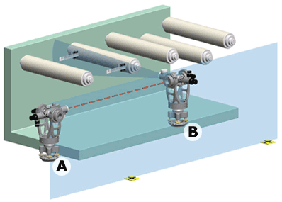
View from above: A and B work together to determine how far each roll
is from being perfectly perpendicular to the machine's centerline.
Step 3
We then hold an optical tooling scale on the side of the roll (near the end), oriented horizontally. Scale bubble levels help us to know that the scale is actually horizontal and that it is placed properly on the roll. We take a measurement on this scale using the micrometer on instrument B. Then we move the scale to the other end of the roll and repeat the process. Taking measurements on each end of the roll will reveal the degree to which the roll is not parallel to B's line of sight. We know that the roll must be parallel to B's line of sight in order to be perpendicular to the machine centerline.
When we are finished with this roll, we simply move transit B over to the next roll. Sometimes more than one roll can be measured without moving the instrument (ex., measuring the right side of one roll and the left side of another). Since A is still aligned with the offset centerline, all we have to do is to set up B in another position and re-collimate to A. In this manner you can check an entire row of rolls or other components for parallelism to any given reference.
(Note: There are other ways to establish the original reference line if no offset centerline exists. Any trusted datum can be used. Sometimes an approximate centerline can be created over the length of the machine by locating the center of near and far rolls. Sometimes rolls or frame components which are difficult or impossible to adjust are used as the reference, to bring everything else parallel to them. Or, transit B could be set parallel to an arbitrary roll, and all rolls measured against that reference. After all rolls are measured, it can be determined which ones should be adjusted.)